
Design and Concept Development
You can get a great sense of achievement from making a piece to someone else’s plans, but
there is a special buzz from designing and making from scratch. Knowing that the piece
would not exist if you hadn’t thought about it, developed the design and then worked the
wood is very sasfying. However many woodworkers miss out on this, partly because they
lack condence in their design abilies and also because they are unsure about how to get
from the idea to the wood.
It’s quite dicult to teach design, not that it’s necessarily insncve, more that design intuion
comes from experience; seeing others work, thinking about proporon, understanding how the
parts come together as a piece is built, geng a feel for what looks right. People have wrien
thick books on this so, in the scope of this book, I can only give some pointers that can set you
on the road to an understanding of design.
The design process, by which I mean the path from the inial wish to build something to the
moment you pick up the saw to start cung out the parts, can be divided into ve stages:
Idencaon of need and development of design parameters.
Research.
Design brain storming.
Design review, based on:
Aesthecs
Funconality
Construcon consideraons.
Design development.
In the rest of the chapter we will develop these further.
Idencaon of need and development of design parameters.
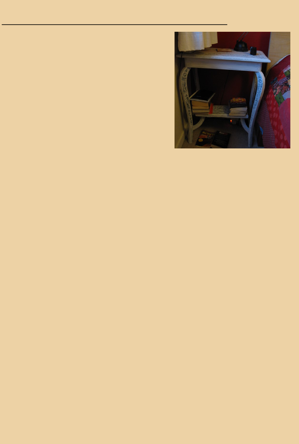
As an example for this “chapter” let’s imagine I want
to replace the rather shabby chic bedside table in my
bedroom. (This was the orginal premise when this
chapter was wrien a bedside cabinet was also to be
one of the projects for the book so construcon had to
be fairly simple for a beginner to tackle. Unfortunat-
ley neither chapter nor project made it into the book).
To start I need to dene some of the requirements for
the table ie funconal and stylisc consideraons.
Some of the factors might be:
The height of the bed will probably decide the
height of the table/cabinet.
What do I need to keep by the bed:
Do I have a bedside light.
How much other space is needed on the top for drinks , alarm clocks etc
Do I have lots of bedme reading, are they books or just a Kindle.
Do I have other items you keep by the bed, tablets, mobile, condoms.
Do I want the piece to look dy or can it be more “cluered”.
What is the other furniture in the bedroom like, is there a strong style or dominant wood.
Should the piece back right up to the wall and if so, how wide is the skirng board.
In consultaon with my beer half I have come up with the following parameters.
The height to the top of the maress is 600mm
The top should be large enough for a bedside lamp, alarm clock, cup of tea and the book
currently being read in bed.
There should be storage below for other books read or waing to be read. They do not
need to be hidden as long as they look dy.
There is not a denite style in the room. The bed is made in birch ply and the dressing ta-
ble is stripped Edwardian pine. The rest of the house has a contemporary style.
The skirng board is minimal so not really a consideraon.
Let’s get rid of this!
Research.
Having decided on what I want the bedside table to do and what the stylisc parameters might
be I can start researching various approaches to address these factors.
I could start by looking to see how others have addressed a similar brief. This can be done in vari-
ous ways.
Looking for images of the piece I’m designing. I could do this in a number of ways.
Google the piece to see what comes up.
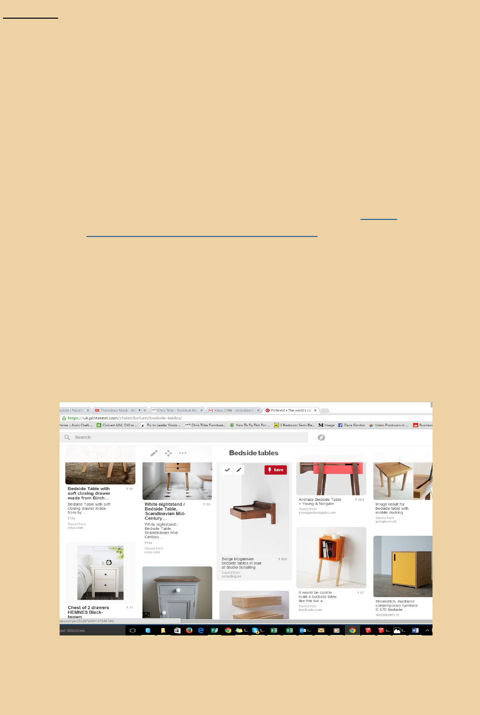
Many professional designers use Pinterest as an element in their research. On
Pinterest you can build your own porolio of preferred designs (a quick look at
Pinterest showed a bedside cabinet with built in plug in points for mobiles etc,
useful). The pintrest board I made for this can be seen at hps://
uk.pinterest.com/christribefurn/bedside-tables/
Look at catalogues either paper or online.
Check out the style magazines.
Visit furniture shops to get a feel for pieces in the round (or square!). If I see something
I like I would consider what features are aracve, similarly what is it about a piece
that I don’t like. These preferences can be reected in my design. I might take some
surrepous pictures.
Screen shot of part of my bedside table Pintrest board

Furniture is usually built for human interacon so ergonomic consideraons need to
be part of the research, parcularly in relaon to tables, desks and chairs . Although
perhaps not signicantly for the bedside table.
Research the physical properes of the materials available. For instance:
What is the deecon strength. As an example for book shelves you need to
know how thick the shelves need to be to support the weight of books, this will
decide both thickness and length of shelves. The Sagulator is a good online re-
source for this hp://www.woodbin.com/calcs/sagulator/
Is the mber subject to excessive movement due to humidity. The Shrinkulator
is another good online resource for dening wood movement hp://
www.woodbin.com/calcs/shrinkulator/
How does in react to moisture (chipboard will fall apart)?
Does it work easily ie will you be able to cut and plane it during making?
Does it take screws and xings easily? MDF and chipboard have no strength for
screws driven in from the side.
Will it stain and take a nish easily?
Will there be any special nish requirements?
These are all factors that will need to be considered in the design review and development stag-
es.
Design brain storming (are we allowed to say that!)
It may be that you have found exactly the design you want whilst researching. If so you can
skip this bit. Otherwise you should have various ideas milling around in your head. These
need to be recorded. This can be the dicult bit for some people as they lack condence
with drawing, perhaps they were told they couldn’t draw at school. I would urge them to do
it anyway, my drawing is prey rubbish, but I do nd that just geng a rough idea from
head to paper, no maer how badly drawn, helps to see whether the design has possibili-
es. You can develop it later to see if it really works. Also you will nd that once you start
drawing your skills will improve. I have tried doing this stage using sketchup but nd that
this tends to se the ow of ideas, you can sketch an idea with a pencil more quickly than
you can with a mouse.

Get a large sketch pad and pencils (I usually use A3 pad and H and HB pencils, H for guide lines
and HB for highlighng the nal drawing) and draw out your ideas, trying not to censor yourself
too much. You could draw side and front views to express your idea or try a perspecve ap-
proach. For perspecve it can be useful to start with blocking out the form. The bedside cabinet/
table is good for this, the basic form of the piece is likely to be an elongated box, draw this, then
sketch in the features of the parcular design. If you wanted curves they could be added to the
basic form.
Try not to think about the complexies of design or construcon problems at this stage, you can
deal with them later. We want the creave juices to ow unchecked! Oen it is useful to think
about other forms than furniture when designing; architecture, engineering and natural forms
can be sources of inspiraon. I remember that for a period I had to spend long journeys vising
aging parents, I whiled away the me designing speculave furniture in my head. I ended up for
a while making pieces that looked vaguely like motorway bridges!
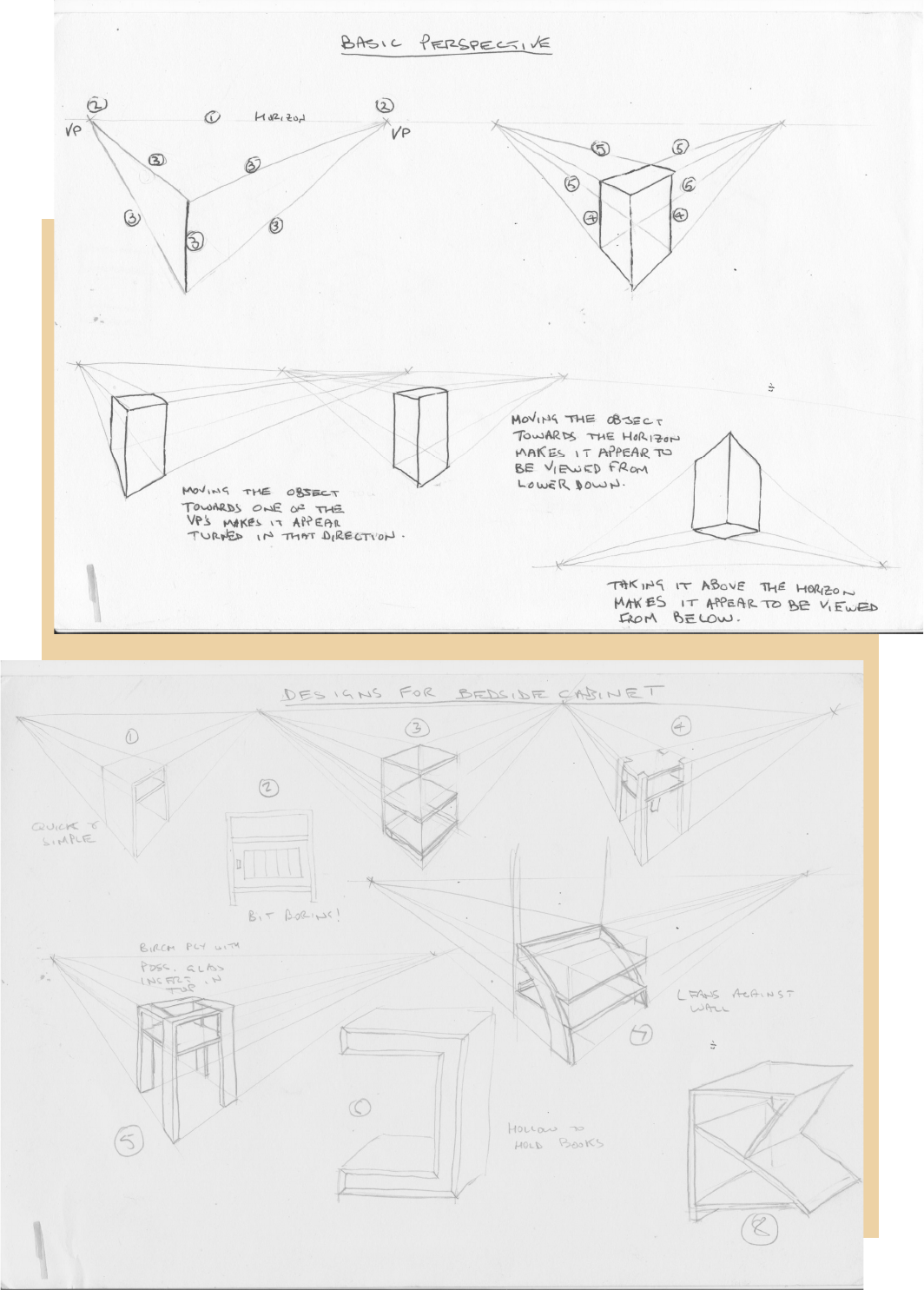
On the next page are some pages of sketches I did for the bedside table, I did them on an A4 pad
to make reproducon easier. But rstly some help if you are unsure about perspecve.
To draw a box in perspecve (from a self confessed bad draughtsman!)
Refer to the drawing on the next page when reading this the numbers on the xrawing refer
to the instrucon number.
1. Take a sketch pad and draw a horizontal line high up the page, this is your horizon.
2. Now mark two points on the horizon to either side of where the box is to be drawn,
these are your vanishing points (VP).
3. Draw a vercal line to represent the front corner of the box and trace lines from each
end back to the VP’s, these are your perspecve lines.
4. The side corners of the box can be drawn in vercally stopping where they intersect
with the perspecve lines.
5. Now trace lines from the ends of the side corners back to the opposite VP’s. Where
they intersect is the back corner. Draw in the corner to complete the box.
6. Having one VP closer to the box and the other further away will turn the box eg if
the right hand VP is further from the box it will cause the box to appear to be viewed
more from the right. Also moving the horizon up will make the box appear to be
viewed from a higher point. It’s quite interesng to play around with changing the
horizon and VP’s to see what eect it has.

Design review.
The dierent designs can now be reviewed based on aesthecs, funconality and construc-
on consideraons. During this review the merit of the dierent designs will become evi-
dent. It may be an iterave process, the design being tweeked and reconsidered. The review
should ask the following quesons.
Aesthecs
Does it look good, is it aesthecally pleasing, this may be a maer of opinion. For instance I
quite like design 7 (the proporons need changing in the drawing), my wife hates it. We agree
design 2 is boring. Perhaps the design can be amended to improve its appearance. It is at this
stage that the materials to be used could be considered. Dierent woods will change the feel
and look of a piece.
Funconality
Does the design actually full the funconal requirements dened in stage one. For instance
design 6 may look OK but I’m not sure it will not hold the number of books required.
Construcon consideraons
Does the design work as a structure? This is a vital consideraon, oen good looking designs
fall by the wayside because of technical or material problems. It is while asking this queson
that you will dene the materials to be used. The maers for consideraon here are:
1. How will the piece be jointed and are the members strong enough to joint? eg
Mdf and chipboard will not hold screws into the side of the board, it is dicult to
get a strong morce and tenon in thin secon pieces, if the design calls for very
thin legs it may be worth making them in metal rather than wood. I think design
3 may not be strong enough, it needs more support for the shelves.
2. Will there be problems with wood movement. In my experience the biggest
cause of defects in solid wood furniture is a failure to cater for dimensional
change caused by changes in humidity. This is dealt with in a separate panel.
3. What hardware is available to help with construcon? In the bedside table pro-
ject for instance we may have a drawer and door so what sort of hardware
should we use, concealed hinges or bu hinges, metal drawer runners or tradi-
onally ed drawers.
4. Are the construconal requirements within your capabilies? Do you have the
skills and equipment to make the piece.
Of the designs shown I quite like 5 . It has visual interest, the glass insert would be good for
hot cups etc. I could see it working in birch ply so there would not be movement problems. It
will also be straight forward to make.

Dealing with wood movement.
Wood is constantly on the move, it expands and contracts across the grain depending on the hu-
midity of it’s surroundings. For instance a metre wide oak table top make shrink by 9-10mm when
going from say 10% moisture content in the summer to about 7% in winter when the house is shut
up with the radiators on, rather like a kiln! The movement may not be just dimensional, there may
also be cupping across the grain where the wood curls slightly. Ignoring the eects of movement
when designing furniture will cause problems in the future, so how can we deal with this
There are a number of ways to avoid, migate or cater for this movement.
1. Use man made boards. Man made boards such as ply wood, chip board and MDF are
not eected signicantly by changes in humidity. This is one of the main reasons so
much mass produced furniture is made in chipboard and MDF. It allows the manufac-
ture of designs with large at surfaces that will not be aected by movement due to
humidity. However cauon must be taken when mixing solid wood with man made.
Firmly xing solid wood across the grain to manmade will cause issues such as warping
and cracking if the solid moves.
2. Use more stable woods. Some woods move more than others and movement will
also vary depending on how the wood is cut from the log. This was menoned in chap-
ter one of the book. Oak and walnut for instance are prone to movement whereas
cherry, teak and cedar are less prone. However I would not recommend that you base
your species choice on movement alone. The cut of the board will also aect move-
ment, a quarter sawn board will be much more stable than plain sawn. For instance
the shrinkage from green to oven dry in American white oak is 4% on quarter sawn and
8% in plain sawn. In situaons where stability is important eg tradionally ed draw-
er sides, it is a good idea to use quarter sawn wood.
3. Cater for the movement. Unl the development of man made boards furniture makers
had to allow for movement in their designs. Many of the features that make anque
furniture interesng are there to migate movement. Doors are a parcular problem.
If you make a door in solid wood it is likely to warp so it will be twisted in the opening.
It is also likely to expand and contract so somemes it is lose in the opening and at oth-
er mes wedges in the opening. This is usually deal with by making the door as a frame
and panel. The panel is ed into a groove on the inside of the frame and allowed to
oat within the frame. In the Tudor style cabinet on the following page you can see
that the doors, although quite decorave are in fact frame and panel construcon. Al-
so the side panels are made in the same way.

Twisng and cupping of table tops can also be a problem. Tradionally this was
controlled by ng bread board ends. These are cross grain members ed to
the end of the table using a pegged morce and tenon construcon. The pegs
toward the outside of the top will be ed into slots so they can move as the top
expands and contracts. This means that the top may overshoot the end in dry pe-
riods and vice verse in damp (although before central heang this variaon would
not have been so great).
In the side table project in the book we had to allow for the movement of the
top. This was achieved by ng it using either “L” shaped stretcher plates with
slots in them or “buons” with a spigot that engages with a slot on the inside of
the rail. This meant the top could move even though it was aached to the rigid
undercarriage.
Breadboard ends. From Patrick Dreher—Pintrest
Wooden “button” ts into slot and is screwed home to
clamp the top to undercarriage and allow for movement.
Design development.
So you’ve selected the design that you like, but how do you get from there to actually
starng to make it. Before you start cung the wood you should make sure that the de-
sign can actually be made and also create a cung list. To do this you need to make an
accurate drawing. Tradionally this was a life size workshop drawing or rod. This has
been replaced by computer aided design (CAD) in professional workshops. Professional
CAD packages are very expensive, however there is a very good free 3d design package,
Sketchup. It is fairly easy to learn the basics of Sketchup, making it widely used by stu-
dent’s and hobby woodworkers. As there are numerous sketchup tutorials and forums
on the internet I will not deal with it in the limited space here.
Sketchup is useful for dening a selected design. Somemes a rough pencil drawing can be
misleading and when you draw out the piece accurately it does not t together, rather like
Escher’s triangle! It is whilst drawing the piece accurately that nal decisions about how
the piece will be jointed are made. Some makers work straight from the CAD or sketchup
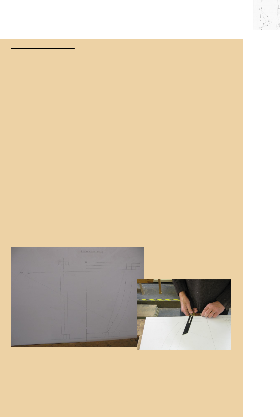
drawing. However it can sll be useful to draw up a life sized workshop drawing. I use
sketchup but sll make working drawings, perhaps I’m a bit old fashioned but I nd the
drawing useful as I can actually oer pieces up to it to mark out or check I have cut them
correctly, for angled pieces I can set my sliding bevel directly from the drawing, for curved
work I can check a template is correct my placing it directly on the drawing. The workshop
drawing shown below is of a circular table with angled and curved legs, it’s invaluable for
checking and seng out.
If you’re making a small piece like a jewellery box the three elevaons can be drawn easily
on a board. If it’s larger, a chest of drawers or even a kitchen perhaps, the board would be
large and unwieldy. There is a method of drawing the measurements for each dimension
(height, width and depth) on a narrow strip of board, known as drawing a rod. The idea is
that the board is divided into three strips represenng the three dimensions. For each di-
mension you drawing the component measurements for that parcular dimension.
The selected design for the bedside table is not a very good example for demonstrang draw-
ing up a rod so as an exercise we will use the side table project (page 236 in the book) as an
example for drawing a rod. This could be done as a full size drawing, I am showing it as a rod
for explanaon purposes. It may be worth referring to the project drawing in the book when
reading the following panel.
Drawing up a full size Rod.
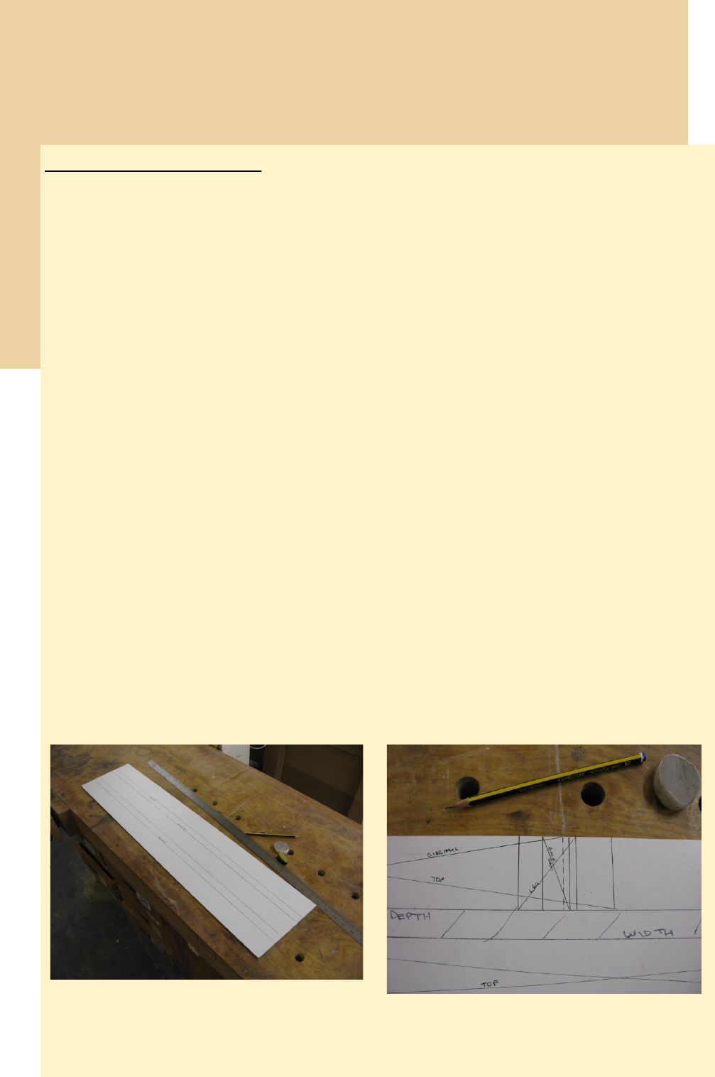
Prepare a board slightly longer than the largest dimension of the piece of furniture. In our case
this would be the height, about 840mm, so let’s make the board 860mm long. The board can be
quite narrow, about 200mm. I use 2mm white painted MDF but any board will do.
1. On the board draw three strips about 50mm wide and mark them Height, Width and
Depth.
2. We will start by marking out the width dimensions.
A. From the le hand end measure the width of the top, 800mm, and square this
across the width strip. Draw a diagonal line from corner to corner of the rectangle
formed.
B. The legs are posioned 27 mm from either edge of the top. Mark the outside face of
the leg at either end then the inside face 43 mm from this. Mark a diagonal on the
rectangles formed.
C. The front and back rails have a 32mm tenon at either end. Mark a dashed line 32
mm in from the inside faces of the legs. This indicates the ends of the rails. Draw a
diagonal line from end to end.
D. Finally we need to mark in the posion of the side rails at either leg. They are set in
5mm from the outside edge and 20mm wide so mark lines 5mm and 25mm from
the outside edges and indicate with a diagonal line.
The diagonals indicate the extent of the components. You could mark on the diagonals
which component they refer to.
Board prepared for drawing the rod.
Right hand end of depth rod showing from the right:
the end of the top, outside edge of leg, outside edge of
front/back rail, end of side rail (dashed), inside edge of
front/back rail, inside edge of leg
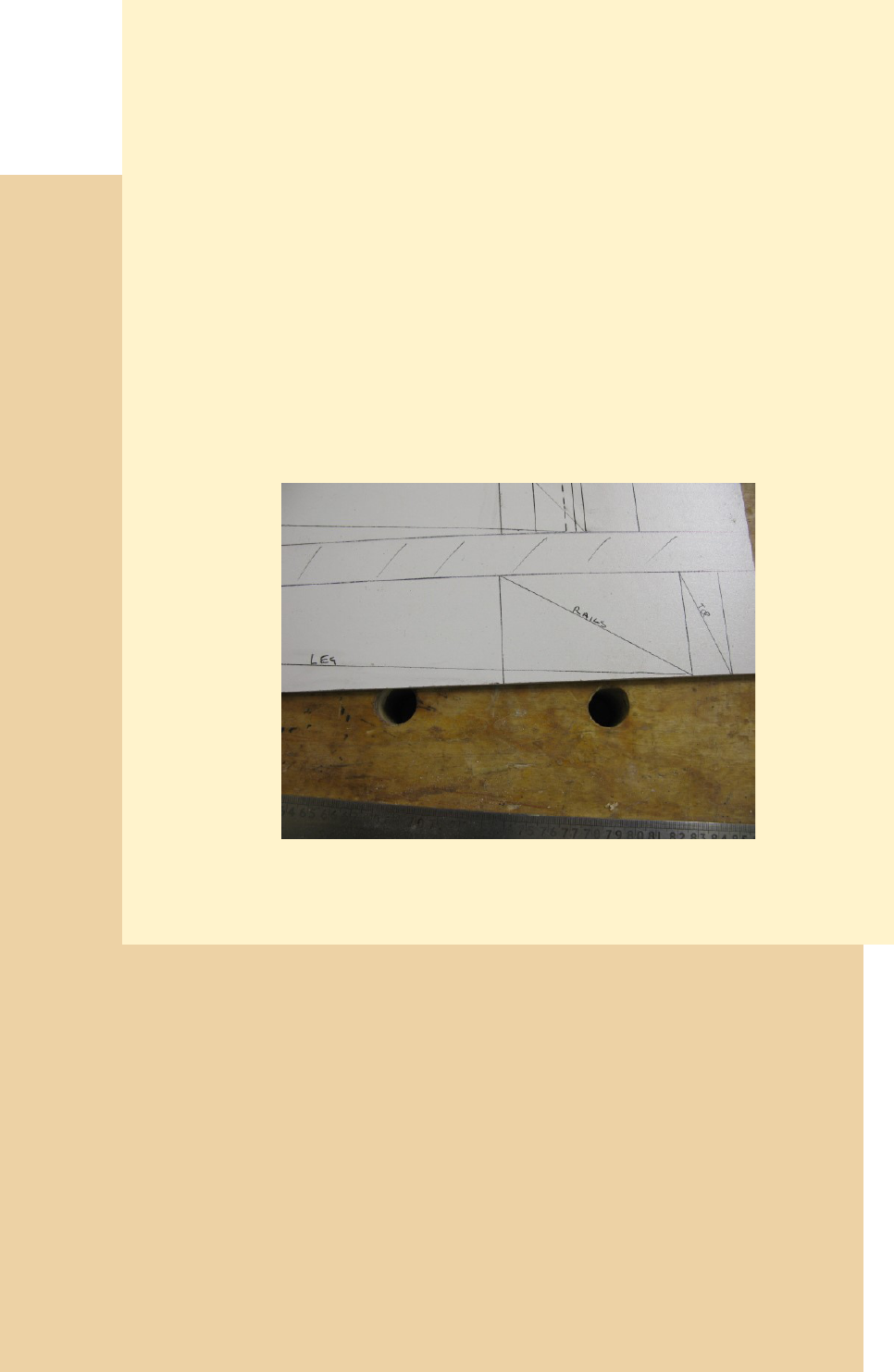
The eagle eyed amongst you may have spoed a slight inconsistency, on the drawn rod the
rail lengths come out at 724 and 324 mm when the cut list in the book shows 726 and 326mm
(this will be corrected in later edions of the book!)
I hope this explanaon is not too confusing. In my teaching career I have oen explained
drawing up rods and I’ve always found it a dicult concept to get across.
Rods like these are especially useful when making ed furniture as the boards can be physi-
cally oered to the opening the furniture is to occupy and the crical dimensions such as
width, depth and posion of pipework and sockets marked . This helps to avoid the embar-
rassing situaon of making a piece then nding it doesn’t t!
3. Hopefully you will have noced that we have only specied the measure-
ments for just one dimension, the width of the table as viewed from the front.
For instance the side rail, is only indicated by the 20mm thickness face on the
leg, the width of the rails is not relevant in this dimension, it will be specied
in the height dimension
4. The depth dimensions can be laid out in a similar manner to the width.
5. The height dimensions are fairly simple.
A. From the le hand end mark the length of the leg, 820mm, and indicate
with a diagonal
B. Inside the right hand end of the leg mark the posion of the boom of the
rail, this will be 90mm from the top end.
C. Finally mark the thickness of the top, 20mm, beyond the end of the leg.
The right hand end of the height rod showing from right to
left: top, rail, then diagonal indicating length of leg.

It is now possible to pick up all the dimensions for a cung list from the dierent dimension
strips. For instance the length of the front/back rails from the width strip, the thickness from the
depth and the width from the height. If you are more technically minded you could do this from
the sketchup drawing, possibly using the sketchup extension Cutlist.
Once you have a cut list you are ready to start making. You should have worked out how the
piece will be constructed during the stages of design, your rods, workshop drawing or sketchup/
cad drawings should act as a reference during the making process.
